|
|
Notice: Please do not plagiarize our information. We've seen a lot of our website information posted on other sites, including repair business websites. We've literally spent years collecting repair data, writing and updating our website to help GPS owners. If you wish to refer to the information on our website, please add a referrer link to our site and give us proper credit. Thank you!
General Charging Information:
Most GPS's can be charged by (3) methods:
AC Wall Charger (preferred)
DC Car Charger (preferred)
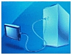
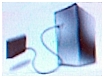
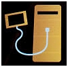
USB to PC Cable (not preferred)
The best method to charge your GPS is using either the AC wall charger or DC car charger. We typically do not recommend using the USB port to charge your GPS. Some PC USB ports can not provide the amount of current required to charge your GPS.
AC Wall Charger Problems:
The AC charger is a non-user servicable charger. That means it wasn't designed to be serviced by the user. If your AC charger fails, your best bet is to purchase a new one. It's not worth the time and aggravation of trying to take it apart and fix it.
The AC charger is a small power supply that contains a transformer that steps down the incoming AC input. The stepped-down AC is rectified to DC and applied to a +5 VDC regulator circuit that provides 1 Amp of current to charge your GPS's internal lithium-Ion battery. When your AC charger is working correctly, you hear a beep and you will see a yellow lightning bolt symbol over the green battery bar graph, which is viewed on the main menu screen (G-Brand, 3xx & 6 models). On 2xx models, you will hear a beep and the battery icon will go away, indicating you are no longer on battery power.
DC Car Charger Problems:
The DC car charger plugs into a standard automotive cigarette lighter receptacle and converts +12 VDC to +5 VDC to charge your GPS's internal lithium-Ion battery. When your car charger is working correctly, you will hear a beep and you will see a yellow lightning bolt symbol over the green battery bar graph, which is viewed on the main menu screen (G-Brand, 3xx & 6xx models). On 2xx models, you will hear a beep and the battery icon will go away, indicating you are no longer on battery power.
If your DC car charger is plugged into the cigarette lighter receptacle and you don't hear a beep and you don't see the yellow lightning bolt symbol over the green battery bar graph (3xx & 6xx models) or the battery bar graph doesn't go away (2xx models), then you should make sure you have +12 VDC at the receptacle. Try plugging something else into the receptacle. If the other device works, then the receptacle is good. If the device doesn't work, then I would check your cigarette lighter fuse in your vehicle's fuse box.
If the cigrarette lighter receptacle has been determined to be in working order, then most likely the problem is with your GPS's DC car charger. Is there a LED that lights when you plug it into the receptacle?
There is a fuse in the tip of the DC car charger. In most units, the tip unscrews and you will find a glass fuse behind the tip. CAUTION!! be careful when unscrewing the tip. The tip is spring-loaded and if you're not careful, the tip, fuse and spring will shoot across the room! If you don't know what parts were ejected, you won't know what to look for when you are on your knees looking for the parts. Unscrew the tip slowly and let the parts shoot into the palm of your hand.
Take the glass fuse out and hold it up to the light. There is a thin wire inside that runs from one end to the other. If the wire is broken, the fuse is bad and needs to be replaced. Sometimes the glass will be blackened, showing that the fuse blew but that's not always the case. Sometimes a fuse will just break from fatigue. The best way to check a fuse is with an ohmmeter. A good fuse will read (0) zero ohms. A bad fuse will read infinite resistance.
If the fuse is bad, replace it with the exact value of the original fuse. You will find the rating stamped into the side of one of the metal ends of the fuse. It will say something like "1A" (1 Ampere). You can purchase replacement fuses at any Radio Shack, Home Depot, Lowes, automotive store or hardware store. If you're not sure what to buy, just take the fuse with you and ask the store assistant to find the right replacement for you. Buy a few spares and put them in your glovebox, you'll never know when you might need them. G-Brand Car Adapters use a 1A 5x20mm fuse in the tip.
If it has been determined that the DC car charger is operating correctly but you still can't see a yellow lightning bolt symbol on the GPS display, when plugged into the cradle, then there is a possibility that one of the internal pins of the GPS's rear cradle socket has been bent or broken. These pins compress against the internal printed circuit board and apply the +5 VDC to the board (3xx & 6xx models).
The only way to repair this problem is to dissassemble the GPS and replace the entire cradle socket. Please do not attempt to make this repair unless you have the right tools and knowledge of how to take the GPS apart. You take the risk of further damaging your GPS.
Loose/Broken Mini-USB Port:
The USB port has a limited life. After a period of time, the connector will become loose and often, you'll have to wiggle the USB plug around to get your GPS to charge. Although not always practical, we recommend that you charge your GPS with your car adapter cradle. The reason we say this, is because your GPS's car adapter cradle was designed with a spring-loaded connection/mechanism (some G-Brands only), that has a far greater life-span than that of the USB port.
If your USB port has become loose, then it either needs to be resoldered or replaced. This is a surface mount component, which is very difficult to resolder using a standard soldering iron.
Symptoms of a Loose or Broken USB Connector:
1. The unit will be unable to be charged. The unit will not show the charging mode when connected to a charging source and will remain on battery power.
2. The unit may appear to be dead, as a result of the battery not being able to be charged.
3. A PC to GPS icon might be displayed on the screen when connected to a charging source, as if the unit was connected to a PC.
4. Inability to receive traffic data from an external traffic receiver.
Watch our YouTube Video Regarding USB problems

** Attention **
Models 30, 40, 50, 2xx, 2xxW, 11xx, 12xx, 13xx, 14xx, 24xx & 25xx Owners!
These models are susceptible to loose and broken USB ports
The surface mount components (SMD/SMT) on the printed circuit board of the GPS are soldered to the board by running the board through a surface mount oven. This works great for very small components like resistors, capacitors and integrated circuits (IC's) but for components that have a larger mass, the oven may not be able to adequately heat the component to the proper temperature to make a good solder connection.
These parts really need to be soldered by hand with an iron set at a higher temperature. The solder pads for these larger mass components have to be very small so that the oven temperature can solder the connections. The problem with small solder pads is that they provide very poor mechanical support. Making the solder pads larger will provide much better mechanical support, however in doing so, it will also require a greater oven temperature to heat up the larger pads to make a good solder connection.
The USB port is a large mass component that is often not soldered very well to the board. Road vibrations and repetitive insertions and removals of the charger plug from the USB port can put stress on the USB port's solder connections, causing the unit to no longer charge and/or communicate with a PC in data mode. A good sign that you have a USB problem is if the unit shows the computer to GPS icon on the screen or if it keeps popping up with a power shut down screen with the charger plugged into the USB port.
So, what do we do to resolve this problem? Well, if the connector is damaged, we will replace it. We resolder all of the connections by hand and make modifications to the printed circuit board to provide more surface area for soldering. We then apply a bonding material all around the base of the USB port, which increases mechanical stability and locks the connector to the board.
We can also perform this procedure as preventative maintenance to prevent functioning USB ports from breaking in the future.
WARNING! If you suspect that the USB port is defective, please do not try to update your units firmware or map! An intermittent USB port can cause a failed map and firmware upgrade, causing your unit to no longer function. Additional use of the USB port while intermittent, can cause damage to the printed circuit board tracks, resulting in a higher repair bill. Stop using your unit immediately and have it repaired by a professional.
NOTE Please note that sometimes an intermittent charging problem is caused by a broken/intermittent wire in the charger. A damaged/bent charger plug can also cause additional stress on the connector, not only breaking the original connector but also the repaired/replaced connector. Should you decide to have us evaluate this problem, we request that you send the charger as well, so that we can test the entire charging system.
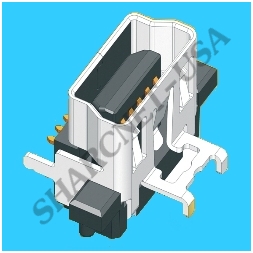
Figure #5A: Mini-USB (3D Model)
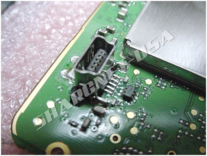
Figure #6A: Mini-USB (front view)
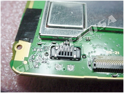
Figure #6B: Mini-USB (rear view)
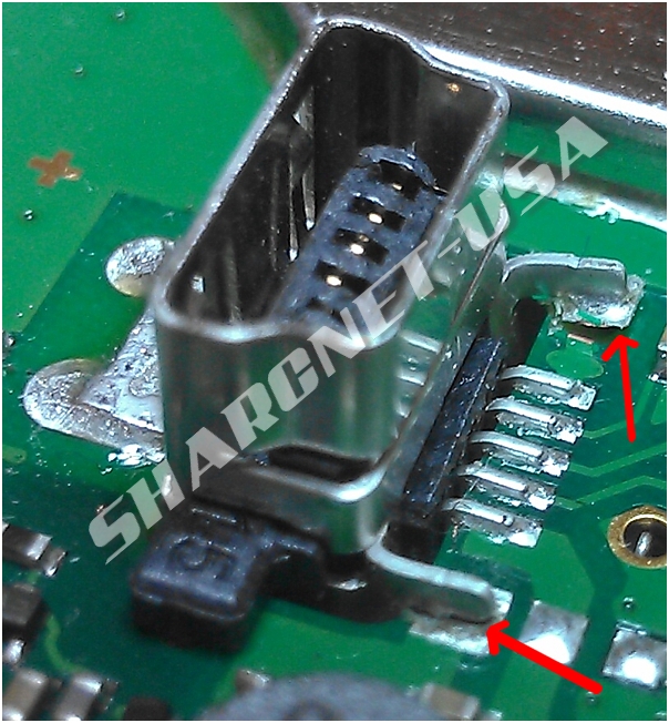
Figure #6C: Mini-USB (loose mechanical legs, data and power pins will break next)
As shown above, the outer mechanical mounting legs have come loose from the board. On one of the legs,
the actual solder pad has been lifted up from the board. Even though all (5) pins of the connector are making good contact with the board, as a result of the loose mechanical legs of the housing, the housing will be able to tilt backwards, causing the charger plug to no longer be pressed against the (5) contacts in the receptacle, resulting in an intermittent connection. Additional rework will be required to restore and reinforce the mechanical connections.
It is just a matter of time before the (5) center data and power leads will also be stressed and will break free, preventing the unit from being able to be powered by the DC charger.
The internal battery will not be able to be charged as well. Eventually, the unit will be dead. Please do not attempt to fix this problem yourself.
It is very easy to overheat the printed circuit board tracks, causing even more damage, possibly to the point of being unrepairable. We are not able to work on units that have been tampered with.
In addition to repairing this problem, we also add reinforcement to the USB connector to help prevent this issue from happening again.
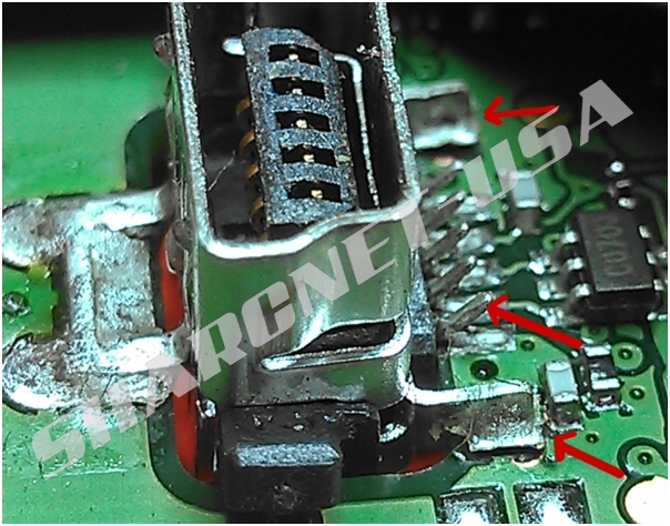
Figure #6D: Mini-USB (Mounting legs, data and power pins broken away from the board)
As shown above, the outer mechanical mounting legs, data and power pins have come loose from the board. Once the battery has been drained, the unit will be completely dead and the battery will not be able to be charged. The unit will not be able to turn on when connected to an external power source.
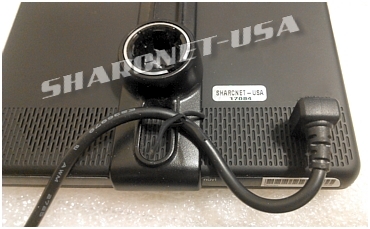
Figure #6E: Charger Plug with Cable Support
We recommend that you secure the charger cable to the cradle, as shown above, using a flat wire tie. The weight of the cable and traffic receiver while driving, can place stress on the USB port and weaken the port.
Computer to GPS Icon on the Screen When Plugged into a Charger:
Figure #6F: Computer to GPS Icon
When you see the Computer to GPS icon on the front display of your GPS, this indicates that your GPS
is in the data mode. While in the data mode, your GPS can communicate with your PC and you can add pictures,
music, new vehicle icons and even upgrade your GPS firmware and map.
You should only see this symbol however, when you are using a USB data cable between your GPS and PC. If you are
seeing this icon when using an AC or DC charger, then there is a problem with the charger or maybe a bad connection on your unit's USB charger port.
While we are not trying to push OEM-only products, we can tell you that there is a difference in wiring between some
generic AC/DC chargers and OEM charger products.
Figure #7: Mini-USB Pin Assignment
On one charger product, the manufacturer ties the X / ID pin to ground (Pin 4) through a 17.3 or 22K resistor. This tells the GPS that
the device plugged into it, is indeed a charger and it will tell the GPS to go into charge mode.
| Pin |
Pin
Name |
Description |
| 1 |
+5VDC |
+5 Volts DC |
| 2 |
Data |
Not connected / Float |
| 3 |
Data |
Not connected / Float |
| X |
ID/GND |
Connected to pin 4 (GND) with 17.3K or 22K ohm resistor |
| 4 |
GND |
Ground |
Figure #8: GPS Mini-USB Mode Connections
In a standard Mini-USB plug, like the USB data cable, the X / ID pin is tied to ground though a 200K resistor, making the GPS thinks it's connnected to a PC and it enters the data mode. When a GPS is in the data mode, it will not charge. Yes, there are ways around this but that's for another discussion. :)
So, if you see the Computer to GPS icon after plugging in either a new AC or DC after-market charger, then you need to replace
the charger with a OEM (Original Equipment Manufacturer) charger or a compatible off-brand. Again, we are not trying to push OEM products but using the OEM product will resolve this issue.
WARNING!!! Taking your GPS apart requires the right tools. There are internal flex ribbon cables for the antenna, touch screen and LCD screen. These cables are very delicate and can be torn easily if you're not careful. The antenna flex ribbon cable runs through the swivel antena shaft and is very delicate. In addition, these devices contain components that are sensitive to static discharges and can be damaged without using the proper grounding techniques. Please do not attempt to make this repair yourself unless your are qualified to do so. We have received numerous emails from people who have gouged and cracked their GPS's case and permanently damaged their GPS's LCD screen and antenna! Save yourself the aggravation and possible damage to your GPS by allowing us to repair your GPS for you.
Please feel free to fill out a Repair Request/Quote Form, which is located at the bottom of the left-hand menu. We'll be more than happy to discuss your GPS problem with you and attempt to offer a possible solution to have the problem resolved.
|